
Easy Switched Power Source
 08-16-2011, 05:55 PM
#1
JK Jedi Master
Thread Starter
If your TIPM (fuse box) is set up like my 2008 is....
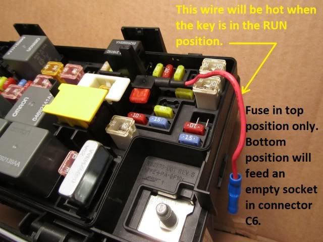
Here is a way to get switched power from the fuse box. It's easier than installing wires in the connector under the TIPM, although not quite as clean an install.
The fuse tap came from Advance Auto, Buss catalog # BP/HHH. It is rated for 10 amps, so that will be the max fuse you should put in it. (edit: I have seen them rated as high as 30 amps, too.)
For use as outlined, only the top fuse position can be used, as the bottom fuse would send power to an empty wire socket in TIPM connector C6.
Last edited by ronjenx; 11-12-2011 at 04:15 PM.


 09-25-2011, 05:29 AM
#6
JK Enthusiast
Join Date: Aug 2007
Location: Houston, TX
Posts: 356
Likes: 0
Received 0 Likes
on
0 Posts
Thanks for the post. I like the how clean this is. I do have two questions...
When you say use the top fuse location only, I am not sure what you mean? Can I not install three of these if needed in the three positions shown here?
Why would it matter if the load side runs to an empty spot in the TIPM?
My other question is how did you run the cable out of the box? Did you drill a hole and then silicone it to keep water tight?
Thanks!
09-25-2011, 06:18 AM
#7
JK Jedi Master
Thread Starter
Using the top position only refers to the fuse tap. The top position is the only one with the wire connected to it.
Putting a fuse in the tap's lower position would route power to an unused pin in the connector under the TIPM. There is no problem with that; it would be useless to do it, though.
You can't install three fuse taps in a row because there isn't room to accommodate the horizontal fuse.
There is room to drill a hole in the side of the boxed area around the large terminal, where the main power connects. Run the wire through the new hole, and seal it with silicone.
Last edited by ronjenx; 09-25-2011 at 06:20 AM.
Trending Topics
10-06-2011, 03:39 PM
#8
JK Super Freak
I've been using these fuse taps for years and they are awesome...
I was ready to rewire my Cobra 75 to switched power using your writeup but ran into a minor snag... What is the recommended way to get an accessory wire into the fuse block case (or get the fuse tap's hot lead out) ??
The fuse block case appears to water resistant and I don't want to jeopardize the integrity of the box by drilling hole or notching the seal. I have an assortment of rubber grommets I could use to seal the hole, but before this project escalates, I though it worth waiting for suggestions...
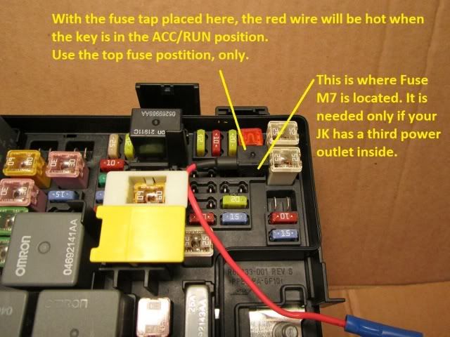
Additionally... My M7, like yours, has three sets of slots.. the center common to a left set and a right set.. yours is pictured in the center/right set and mine is the cener/left set. i have only two accessory outlets.. one switched and one unswitched. Saddling the M7 fuse leaves the new accessory line (red wire) hot all the time.
When I switched the fuse tap to the center/right set as you have it, it was indeed switched to both Acc & to Run. But considering mine was different from the start I don't want to assume it will be fine this way.
M14 (Trailer Tow/BackUp Camera) M9 (Heated Rear Seat) are both open andare hot only when in Run position which isn't what I want for my CB.. I want it hot on Acc or Run...
Thoughts?
I was ready to rewire my Cobra 75 to switched power using your writeup but ran into a minor snag... What is the recommended way to get an accessory wire into the fuse block case (or get the fuse tap's hot lead out) ??
The fuse block case appears to water resistant and I don't want to jeopardize the integrity of the box by drilling hole or notching the seal. I have an assortment of rubber grommets I could use to seal the hole, but before this project escalates, I though it worth waiting for suggestions...
Additionally... My M7, like yours, has three sets of slots.. the center common to a left set and a right set.. yours is pictured in the center/right set and mine is the cener/left set. i have only two accessory outlets.. one switched and one unswitched. Saddling the M7 fuse leaves the new accessory line (red wire) hot all the time.
When I switched the fuse tap to the center/right set as you have it, it was indeed switched to both Acc & to Run. But considering mine was different from the start I don't want to assume it will be fine this way.
M14 (Trailer Tow/BackUp Camera) M9 (Heated Rear Seat) are both open andare hot only when in Run position which isn't what I want for my CB.. I want it hot on Acc or Run...
Thoughts?
Last edited by MikekiM; 10-06-2011 at 04:16 PM.
10-06-2011, 05:42 PM
#9
JK Super Freak
Join Date: Mar 2011
Location: Seattle, WA
Posts: 1,934
Likes: 0
Received 0 Likes
on
0 Posts
Nice write-up!
That's how I tapped from the fuse box to feed and switches that activate the relays that feed the auxiliary lights. They draw very few power so I just a small 5A fuse.
Only problem I had with this solution was routing that tail out of the fuse box. The lid has a double-lip that cover both sides of the lower part's top wall, probably to keep water out.
How did you route that tail without it being "bitten" by the lid? Mine has a dent because of that.
10-07-2011, 05:23 PM
#10
JK Jedi Master
Thread Starter
Nice write-up!
That's how I tapped from the fuse box to feed and switches that activate the relays that feed the auxiliary lights. They draw very few power so I just a small 5A fuse.
Only problem I had with this solution was routing that tail out of the fuse box. The lid has a double-lip that cover both sides of the lower part's top wall, probably to keep water out.
How did you route that tail without it being "bitten" by the lid? Mine has a dent because of that.
That's how I tapped from the fuse box to feed and switches that activate the relays that feed the auxiliary lights. They draw very few power so I just a small 5A fuse.
Only problem I had with this solution was routing that tail out of the fuse box. The lid has a double-lip that cover both sides of the lower part's top wall, probably to keep water out.
How did you route that tail without it being "bitten" by the lid? Mine has a dent because of that.