
Wiring Help Diagram Included
 08-16-2016, 05:01 PM
#21
JK Junkie
I would get what matches the other two switches. If they have both in a matching switch, then it is personal preference. You only need two connections to apply current. I'm not sure what the third connection is except maybe a light in the switch or a 3 way.
 08-17-2016, 02:12 AM
#22
JK Junkie
Just a reminder: Be sure to fuse the pin 87 feeds sized for one light each and I'm guessing the switch 2 feed is already fused with the Rigid flasher harness.
08-17-2016, 01:14 PM
#23
JK Junkie
Thread Starter
Join Date: Mar 2009
Location: Scottsdale, AZ
Posts: 2,368
Likes: 0
Received 0 Likes
on
0 Posts
08-17-2016, 01:44 PM
#24
JK Junkie
No problem. Glad to help. I'm surprised the Rigid flasher didn't come with one.
The switch 1 feed is only going to pull milliamps so you can tap a switched or unswitched source under the dash (using the same gauge wire as the source) which will already be fused. If you decide instead to run a wire all the way from the battery positive to the switch, you should also fuse that wire with a 1A or 3A fuse.
The switch 1 feed is only going to pull milliamps so you can tap a switched or unswitched source under the dash (using the same gauge wire as the source) which will already be fused. If you decide instead to run a wire all the way from the battery positive to the switch, you should also fuse that wire with a 1A or 3A fuse.
Last edited by 14Sport; 08-18-2016 at 02:07 AM.
08-22-2016, 07:00 PM
#25
JK Junkie
Thread Starter
Join Date: Mar 2009
Location: Scottsdale, AZ
Posts: 2,368
Likes: 0
Received 0 Likes
on
0 Posts
No problem. Glad to help. I'm surprised the Rigid flasher didn't come with one. The switch 1 feed is only going to pull milliamps so you can tap a switched or unswitched source under the dash (using the same gauge wire as the source) which will already be fused. If you decide instead to run a wire all the way from the battery positive to the switch, you should also fuse that wire with a 1A or 3A fuse.
08-22-2016, 08:00 PM
#26
JK Enthusiast

No problem. Glad to help. I'm surprised the Rigid flasher didn't come with one.
The switch 1 feed is only going to pull milliamps so you can tap a switched or unswitched source under the dash (using the same gauge wire as the source) which will already be fused. If you decide instead to run a wire all the way from the battery positive to the switch, you should also fuse that wire with a 1A or 3A fuse.
The switch 1 feed is only going to pull milliamps so you can tap a switched or unswitched source under the dash (using the same gauge wire as the source) which will already be fused. If you decide instead to run a wire all the way from the battery positive to the switch, you should also fuse that wire with a 1A or 3A fuse.
08-23-2016, 01:44 AM
#27
JK Junkie
Just be aware that using the relays like this doesn't reduce the amperage coming through switch two. That switch is carrying the full load of the Rigid flasher through the red wire. You could add a third relay to switch the flasher if that is a concern for you. Edit: Nvm, I just looked up the flasher. It's only 3A (the lights are 2.5A) so no need for a relay. Considering this, I would jump the two pin 87 feeds together also with a single 3A fuse and a 3A fuse for the flasher feed. I'm surprised they didn't make the flasher a little more stout. So now you have to fuse it with 3A which means the flasher could blow before the fuse potentially. You can't go down to a 1A because the lights themselves draw 2.5A. The 3A they report in the specs must be the operating amperage and not the maximum amperage. So if you keep blowing the 3A fuses you should be fine to bump up to 5A but you may want to check with Rigid.
Last edited by 14Sport; 08-23-2016 at 03:18 AM.
08-23-2016, 01:54 AM
#28
JK Junkie

Last edited by 14Sport; 08-24-2016 at 02:12 AM.
08-23-2016, 05:40 AM
#29
JK Junkie
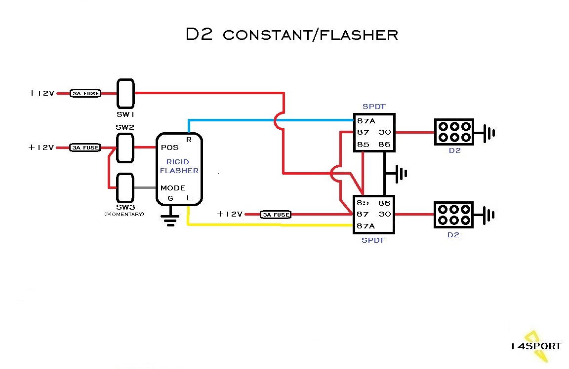
Alright well I went ahead and tested it and everything went as planned. I did not have the D2s or the Rigid Flasher Module so I had to simulate some things. I have a 12V power supply for the battery, two JK side marker lights as the D2s, and a turn signal flasher as the Rigid flasher. I jumped the pin 85s together, the pin 86s together, and the pin 87s together.

The sequence of the test was as follows:
1. Switch 1 on, both lights on
2. Switch 1 off, both lights off
3. Switch 2 on, both lights flash
4. Switch 2 off, both lights off
5. Switch 2 on, both lights flash
6. Switch 1 on, both lights on
7. Switch 1 off, both lights flash
8. Switch 2 off, both lights off.
The purpose of doing it like that was to show you that even if you hit switch 1 while switch 2 is already on, it would not hurt anything. Same if you hit switch 2 while 1 is on, it won't hurt anything but the lights will remain on solid. In other words, anytime switch 1 is on it will override switch 2 making switch 2 useless. Here's a video of the test...
https://www.youtube.com/watch?v=SbogGFK13XM&feature=youtu.be And I drew you up a proper schematic. I think I got it right.
Hope this helps.
Last edited by 14Sport; 08-23-2016 at 01:28 PM.
08-23-2016, 07:01 PM
#30
JK Junkie
Thread Starter
Join Date: Mar 2009
Location: Scottsdale, AZ
Posts: 2,368
Likes: 0
Received 0 Likes
on
0 Posts
Alright well I went ahead and tested it and everything went as planned. I did not have the D2s or the Rigid Flasher Module so I had to simulate some things. I have a 12V power supply for the battery, two JK side marker lights as the D2s, and a turn signal flasher as the Rigid flasher. I jumped the pin 85s together, the pin 86s together, and the pin 87s together. The sequence of the test was as follows: 1. Switch 1 on, both lights on 2. Switch 1 off, both lights off 3. Switch 2 on, both lights flash 4. Switch 2 off, both lights off 5. Switch 2 on, both lights flash 6. Switch 1 on, both lights on 7. Switch 1 off, both lights flash 8. Switch 2 off, both lights off. The purpose of doing it like that was to show you that even if you hit switch 1 while switch 2 is already on, it would not hurt anything. Same if you hit switch 2 while 1 is on, it won't hurt anything but the lights will remain on solid. In other words, anytime switch 1 is on it will override switch 2 making switch 2 useless. Here's a video of the test... YouTube Link: https://www.youtube.com/watch?v=SbogGFK13XM&feature=youtu.be And I drew you up a proper schematic. I think I got it right. Hope this helps.
Holy smokes 14sport thank you so much I owe one big time! I was so afraid my jeep was going to burst in flames I will start assembling the harness tonight will post a video tomorrow!